Table of contents
Acoustic Impedance and Reflection, Worked Through
Acoustic impedance and reflection explained: why boundaries echo, how much energy reflects, why ultrasound needs gel, and how transducer matching layers work.
Ultrasound images are made of echoes, and every echo comes from a place where acoustic impedance changes. Acoustic impedance and reflection explain why a liver looks textured and a cyst looks black, why a probe needs gel to work, why bone casts a shadow and why a transducer has thin layers bonded to its face. The physics fits in two equations. This article works through them with numbers, compares common boundaries, and shows how the same idea shapes both the images and the hardware that makes them.
Key Takeaways
- Characteristic acoustic impedance is Z = ρc, density times speed of sound, measured in rayls (kg/m²/s). Soft tissues are around 1.4 to 1.7 MRayl; air is about 0.0004 MRayl; bone is several MRayl.
- At normal incidence, the fraction of intensity reflected is R = ((Z₂ − Z₁) / (Z₂ + Z₁))². What’s not reflected is transmitted.
- Between soft tissues, R is around 1% or less, so most energy continues and deeper structures can be imaged. Between tissue and air, R is above 99.9%, so a thin air gap blocks the beam.
- Between soft tissue and bone, a large fraction reflects (tens of percent), and what enters bone is strongly attenuated, producing acoustic shadows.
- Transducers use matching layers with intermediate impedance, often a quarter-wavelength thick, to get sound from a high-impedance piezoelectric element into low-impedance tissue. Desilets, Fraser and Kino (1978) gave design rules for broadband matching.
The problem: echoes only happen at differences
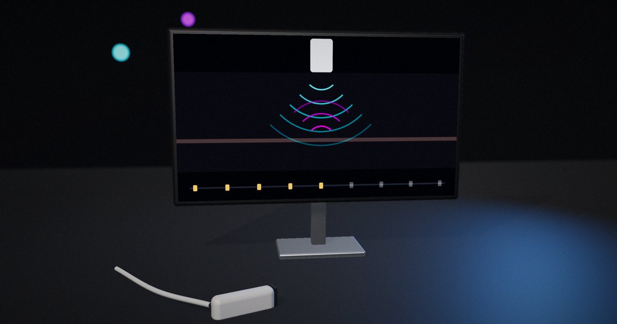
A beam of sound traveling through a perfectly uniform material produces no echo; it just loses energy as it goes. Echoes appear where the material changes. How strong each echo is, and how much energy continues past the boundary, decides what an ultrasound image shows and how deep it can see.
The property that governs this is acoustic impedance. Understanding it lets you predict which boundaries will be bright, which will be faint, where shadows will appear and why the probe has to be coupled to the skin with gel.
How impedance and reflection work
Characteristic acoustic impedance
For a plane wave, the characteristic acoustic impedance of a material is the product of its density ρ and its speed of sound c:
Z = ρ × c
The unit is the rayl (kg·m⁻²·s⁻¹); values for tissues are conveniently expressed in megarayls (MRayl). Compilations of measured tissue properties, such as Goss, Johnston and Dunn’s 1978 compilation in the Journal of the Acoustical Society of America, and Mast’s 2000 analysis of relationships between acoustic parameters in human soft tissues, show that soft tissues have densities close to water’s and speeds within several percent of each other, so their impedances are similar. Fat is lower; bone is much higher; air is lower by more than three orders of magnitude.
Approximate values commonly used for teaching (real tissues vary):
- Air: about 0.0004 MRayl
- Fat: about 1.38 MRayl
- Water: about 1.48 MRayl
- Soft tissue (average): about 1.63 MRayl
- Muscle: about 1.70 MRayl
- Bone: about 7.8 MRayl (wide variation)
- Piezoelectric ceramic (PZT): about 30 MRayl
The reflection coefficient
When a plane wave meets a flat boundary at normal incidence, the fraction of the incident intensity that reflects is:
R = ((Z₂ − Z₁) / (Z₂ + Z₁))²
and the fraction transmitted is T = 1 − R. Haim Azhari’s Basics of Biomedical Ultrasound for Engineers (2010) derives these from the continuity of pressure and particle velocity at the boundary, and they appear in every ultrasound physics text.
Working through common boundaries:
- Fat to muscle (1.38 → 1.70): ((1.70 − 1.38) / (1.70 + 1.38))² = (0.32 / 3.08)² ≈ 0.011, about 1% reflected, 99% transmitted.
- Soft tissue to bone (1.63 → 7.8): (6.17 / 9.43)² ≈ 0.43, about 43% reflected.
- Soft tissue to air (1.63 → 0.0004): (1.6296 / 1.6304)² ≈ 0.999, more than 99.9% reflected.
These three numbers explain most of what an ultrasound image looks like.
Why soft tissue boundaries are faint but useful
Because soft tissues have similar impedances, each boundary reflects only a small fraction of the energy and lets the rest through. That’s what allows imaging of structures several centimeters deep: the beam passes many boundaries and still has energy left. The weak echoes from tissue microstructure, which scatter rather than reflect like a mirror, produce the texture seen in organs. A fluid-filled cyst, with few internal scatterers, returns little and appears dark.
Peter Wells’ 1999 review of ultrasonic imaging in Reports on Progress in Physics distinguishes specular reflection from large, smooth boundaries, which depends strongly on the angle of incidence, from scattering by structures smaller than the wavelength, which returns energy over a wide range of angles. Both depend on impedance differences.
Why gel is needed
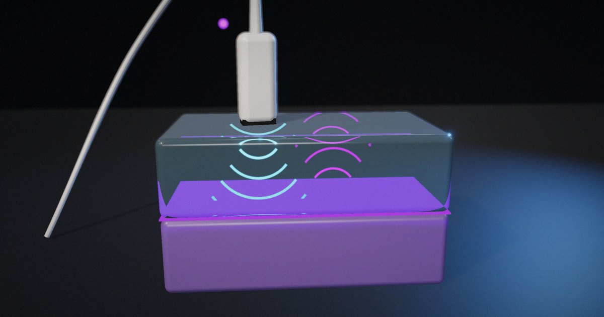
A thin layer of air between the probe and the skin reflects more than 99.9% of the intensity in each direction, so almost nothing reaches the tissue and almost nothing returns. Coupling gel, with an impedance close to soft tissue, removes the air and lets the sound cross. The same physics explains why gas in the bowel or lungs blocks imaging of what lies behind it.
Why bone casts shadows
At a tissue-bone boundary, a large part of the energy reflects, producing a bright echo. The part that enters bone is attenuated much more strongly than in soft tissue. Little energy reaches the structures behind the bone, so the image shows a dark band, an acoustic shadow, beneath the bright surface. Sonographers use shadows diagnostically, for example to recognize gallstones and calcifications.
Angle matters
The reflection equation above assumes normal incidence. At other angles, a specular reflection is sent away from the transducer, and the echo may never return to it, so a smooth boundary can look faint or disappear when the probe is tilted. Transmitted sound also changes direction when the speed of sound differs on the two sides (refraction, described by Snell’s law), which can shift where structures appear.
Matching layers: the same physics in the transducer
A piezoelectric ceramic element has an impedance of around 30 MRayl. Directly against tissue at about 1.5 MRayl, the reflection coefficient would be ((30 − 1.5) / (30 + 1.5))² ≈ 0.82: most of the energy would bounce back into the element instead of entering the body, and the pulse would ring for a long time.
Transducers solve this with one or more matching layers between the element and the tissue. A layer a quarter-wavelength thick, with an impedance between the two, causes the reflections from its two faces to cancel at the design frequency. The classic single-layer choice is the geometric mean, √(30 × 1.5) ≈ 6.7 MRayl. Desilets, Fraser and Kino’s 1978 paper in IEEE Transactions on Sonics and Ultrasonics on the design of efficient broadband piezoelectric transducers derived matching rules aimed at broadband performance rather than a single frequency; their single-layer value, (Z_element × Z_tissue²)^(1/3), gives about 4.1 MRayl for these numbers, and they extended the approach to two layers.
Broadband matching shortens the pulse, which improves axial resolution, and transfers more energy, which improves sensitivity. A backing layer behind the element damps ringing further.
Reflection at common boundaries
| Boundary | Z₁ → Z₂ (MRayl, approximate) | Reflected intensity | What you see |
|---|---|---|---|
| Fat → muscle | 1.38 → 1.70 | ≈ 1% | Faint boundary; most energy continues |
| Water or fluid → soft tissue | 1.48 → 1.63 | ≈ 0.2% | Dark fluid, faint wall |
| Soft tissue → bone | 1.63 → 7.8 | ≈ 43% | Bright surface, shadow behind |
| Soft tissue → air | 1.63 → 0.0004 | > 99.9% | Total block; need for gel |
| PZT → soft tissue (no matching) | 30 → 1.5 | ≈ 82% | Poor transfer, long ringing |
| PZT → single matching layer → tissue | 30 → ≈ 4–7 → 1.5 | Much lower at design frequency | Shorter pulse, better sensitivity |
What to actually do
Teach impedance with three boundaries
Fat-muscle, tissue-bone and tissue-air cover faint echoes, shadows and the need for gel. Work the numbers with learners rather than giving the percentages.
Separate reflection from scattering
Explain that organ texture comes from scattering by small structures, while bright lines come from large boundaries, and that both depend on impedance differences.
Show the angle effect
Demonstrate that a specular boundary fades when the beam isn’t perpendicular. It explains why the same structure looks different as the probe moves.
Connect the hardware to the physics
When explaining transducers, show the matching layer as the same reflection problem solved in reverse: reducing the mismatch so energy crosses instead of reflecting.
What not to do
Don’t present impedance values as exact constants. Tissue properties vary between individuals, organs and conditions; use them as approximate values for reasoning.
How to put it to work
If you have an hour
Calculate the reflection coefficient for five boundaries relevant to your application and rank them from brightest to faintest. Compare with images you have.
If you have a sprint
Build a simple interactive that lets learners pick two materials and see reflected and transmitted energy, then add an angle control and a matching-layer tab. Test it with learners and refine the explanations.
If you want it to last the product’s lifetime
Keep a reviewed table of the impedance values you use in training or product material, with their sources and stated ranges, and update it if better data appear.
The question to ask yourself: “Could a learner predict, before seeing the image, which boundary will be bright, which faint and where a shadow will fall?”
Frequently asked questions
What is acoustic impedance?
It’s a material property, the product of density and speed of sound, that determines how sound is reflected and transmitted at boundaries. It’s measured in rayls, and tissue values are usually given in megarayls.
How do you calculate the reflection coefficient?
At normal incidence, the reflected fraction of intensity is ((Z₂ − Z₁) / (Z₂ + Z₁))², where Z₁ and Z₂ are the impedances on either side of the boundary. The transmitted fraction is one minus that.
Why is gel used in ultrasound?
Because air has an impedance thousands of times lower than tissue, and a thin air layer reflects more than 99.9% of the sound. Gel, with an impedance close to tissue, removes the air so sound can enter the body.
Why does bone show up bright with a shadow behind it?
The tissue-bone boundary reflects a large fraction of the energy, making a bright echo, and the energy that enters bone is strongly attenuated, so little reaches the structures behind it.
What is a matching layer in an ultrasound transducer?
It’s a layer between the piezoelectric element and the tissue with an intermediate impedance, often a quarter-wavelength thick, that reduces the reflection at the element’s face so more energy enters the tissue and the pulse is shorter.
Related reading: how ultrasound measures depth, building an ultrasound echo explainer and do animations teach better than static diagrams?.
Sources
- Goss, S. A., Johnston, R. L., & Dunn, F. (1978). “Comprehensive Compilation of Empirical Ultrasonic Properties of Mammalian Tissues.” Journal of the Acoustical Society of America, 64(2), 423–457. https://doi.org/10.1121/1.382016
- Mast, T. D. (2000). “Empirical Relationships Between Acoustic Parameters in Human Soft Tissues.” Acoustics Research Letters Online, 1(2), 37–42. https://doi.org/10.1121/1.1336896
- Wells, P. N. T. (1999). “Ultrasonic Imaging of the Human Body.” Reports on Progress in Physics, 62(5), 671–722. https://doi.org/10.1088/0034-4885/62/5/201
- Desilets, C. S., Fraser, J. D., & Kino, G. S. (1978). “The Design of Efficient Broad-Band Piezoelectric Transducers.” IEEE Transactions on Sonics and Ultrasonics, 25(3), 115–125. https://doi.org/10.1109/T-SU.1978.31001
- Azhari, H. (2010). Basics of Biomedical Ultrasound for Engineers. Wiley. https://doi.org/10.1002/9780470561478