Table of contents
The 4–20 mA Current Loop Explained, With a Power Budget
The 4–20 mA current loop explained: why current beats voltage, live zero, loop power budgets, NAMUR NE 43 fault levels and HART, with numbers you can check.
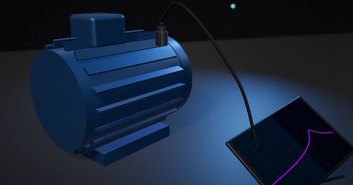
A pressure transmitter 200 meters from the control room reads 12 mA, the PLC shows 50% of range, and nobody needs to know the resistance of the cable in between. That’s the point of the 4–20 mA current loop, a signal standard that has survived decades of digital fieldbuses because it’s simple, robust and easy to troubleshoot with a multimeter. This article explains why current works better than voltage over long cables, what the 4 mA live zero does, how to calculate a loop power budget, what the NAMUR NE 43 fault levels mean, and how HART adds digital communication without disturbing the analog signal.
Key Takeaways
- In a series loop the current is the same at every point, so wire and connector resistance don’t change the measurement, as long as the supply has enough voltage to drive the current through them.
- The 4 mA live zero distinguishes “the process is at zero” (4 mA) from “the wire is broken” (0 mA), and lets a two-wire transmitter power itself from the loop.
- A loop power budget is a voltage budget: supply voltage minus the transmitter’s minimum operating voltage, divided by the highest current the loop will carry, gives the maximum loop resistance.
- NAMUR NE 43 standardizes failure signaling: measurement information between 3.8 and 20.5 mA, and failure at or below 3.6 mA or at or above 21 mA.
- HART superimposes a 1 mA peak-to-peak FSK signal (1200 Hz for a 1, 2200 Hz for a 0, 1200 bit/s) that averages to zero, so the analog value is unaffected.
The problem: voltage signals don’t survive long cables
A sensor that outputs 0–10 V works on a bench. Over a long cable to a control room it runs into three problems. The cable has resistance, so any current drawn by the receiver drops voltage along the way. Ground potentials differ between the field and the control room, so the receiver may see an offset. And a long cable picks up noise, which adds directly to the voltage.
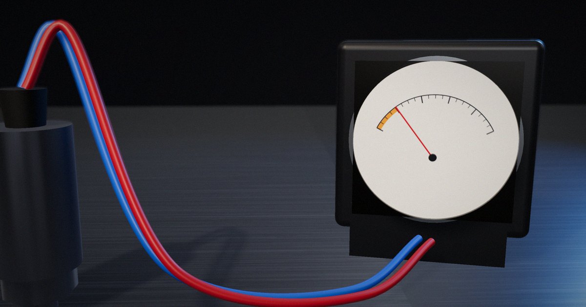
A current signal avoids the first problem completely and reduces the others. The transmitter regulates the current in the loop to represent the measurement. Kirchhoff’s current law says that current is the same everywhere in a series circuit, so the receiver, which measures the current (usually as the voltage across a precision resistor), gets the same value regardless of the cable’s resistance. The loop is also a low-impedance circuit, which makes it less sensitive to capacitively coupled noise than a high-impedance voltage input.
What the standards define
The signal range
The 4–20 mA range is defined in international and national standards for analog signals between process instruments, including IEC 60381-1, Analogue signals for process control systems – Part 1: Direct current signals, and ANSI/ISA-50.00.01, Compatibility of Analog Signals for Electronic Industrial Process Instruments. Their purpose is interoperability: a transmitter from one manufacturer and a receiver from another agree on what a current means.
The mapping is linear. 4 mA is 0% of the configured range and 20 mA is 100%, so the span is 16 mA:
- 8 mA = 25%
- 12 mA = 50%
- 16 mA = 75%
A transmitter ranged 0–10 bar outputting 13.6 mA is reporting (13.6 − 4) / 16 × 10 = 6.0 bar.
Why the zero is “live”
Starting the range at 4 mA instead of 0 does two things. First, a reading of 0 mA can only mean a fault (a broken wire, a failed supply, a dead transmitter), never a legitimate measurement. Second, a two-wire transmitter has to run on the loop current itself, and 4 mA gives it something to run on. Joseph Wu’s 2023 TI application note on HART notes that loop-powered transmitters must operate on less than 4 mA, usually under 3 mA, and that because currents around 3.5 mA can be used to signal errors, the practical power budget is about 3 mA for the entire transmitter, including sensor, converter, processor and output stage.
NAMUR NE 43: signaling failure in the current
Before NAMUR’s recommendation NE 43, Standardization of the Signal Level for the Failure Information of Digital Transmitters, manufacturers signaled faults in different ways, and a control system couldn’t reliably tell a real low reading from a failed instrument. NE 43 (most recently revised in 2021) divides the current range into zones:
- 3.8 to 20.5 mA: measurement information, including a small range beyond 4 and 20 mA for readings slightly outside the configured span.
- At or below 3.6 mA, or at or above 21 mA: failure information.
- Between 3.6 and 3.8 mA, or 20.5 and 21 mA: a margin between the two.
A receiver configured for NE 43 treats a current in the failure zone as an instrument fault rather than a process value, and the transmitter can be configured to drive its output low or high on failure, depending on which is safer for the process.
HART: digital data on the same wires
The HART protocol, maintained by the FieldComm Group, superimposes digital communication on the 4–20 mA loop. It’s based on the Bell 202 modem standard and uses frequency-shift keying: in Wu’s description, a 1200 Hz tone represents a 1 and 2200 Hz a 0, at 1200 bit/s, with a nominal amplitude of 1 mA peak to peak. Because the FSK signal is phase-continuous and averages to zero, the analog value read by a receiver with appropriate filtering doesn’t change. The FieldComm Group describes this as two simultaneous channels: the analog signal for the primary variable and a digital channel for configuration, diagnostics and additional variables.
HART needs some resistance in the loop to develop a readable voltage from the FSK current; the TI note gives a loop resistor range of 230 Ω to 600 Ω, with 250 Ω typical.
A loop power budget, worked through
The question every loop design must answer is whether the supply can drive the highest current through everything in the loop while leaving the transmitter enough voltage to operate. Illustrative numbers:
- Loop supply: 24 V.
- Transmitter minimum operating voltage (from its datasheet): 10.5 V.
- Highest current the loop must support: 22 mA (a high-side failure signal above 21 mA, with margin).
- Receiver sense resistor: 250 Ω.
- Cable: 200 m of conductor in total (100 m out, 100 m back) at about 36 Ω/km for 0.5 mm² copper, about 7.2 Ω.
Maximum total loop resistance = (24 − 10.5) V / 0.022 A ≈ 614 Ω.
Actual loop resistance = 250 + 7.2 ≈ 257 Ω, well within the budget. The voltage left at the transmitter at 22 mA is 24 − 0.022 × 257 ≈ 18.3 V, comfortably above 10.5 V.
Now add an intrinsic-safety barrier with, say, 300 Ω of series resistance and a panel indicator with 100 Ω: the loop resistance becomes about 657 Ω, which exceeds the 614 Ω budget. At high currents the transmitter would run out of voltage and the reading would clip below the true value, a fault that appears only when the process goes high, which is usually when it matters. This is why the budget should be calculated at the failure current, not at 20 mA.
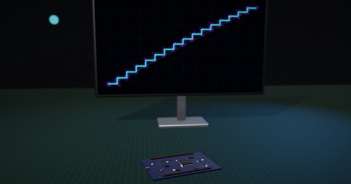
Resolution is worth checking too. 0.1% of the 16 mA span is 16 µA, which across a 250 Ω resistor is 4 mV. The receiver’s converter and the resistor’s tolerance and temperature coefficient decide whether that’s resolvable.
4–20 mA compared with other ways to send a measurement
| Property | 0–10 V voltage | 4–20 mA current loop | 4–20 mA with HART | Digital fieldbus or Ethernet |
|---|---|---|---|---|
| Effect of cable resistance | Error proportional to drop | None while within the voltage budget | Same as 4–20 mA | None (digital) |
| Broken-wire detection | Ambiguous at 0 V | 0 mA is clearly a fault; NE 43 adds fault levels | Same, plus digital diagnostics | Communication loss detected |
| Power to the sensor | Separate wires usually | Two-wire transmitters powered by the loop | Same | Depends (some provide power) |
| Values per pair of wires | One | One | One analog plus several digital | Many |
| Troubleshooting | Voltmeter | Multimeter in series or clamp meter | Plus a HART communicator | Protocol tools |
| Typical use | Short runs, panels | Process transmitters and actuators | Process instruments needing remote configuration | New plants, high-data devices |
What to actually do
Calculate the budget at the failure current
Use the transmitter’s minimum operating voltage from its datasheet, the highest current the loop will carry (including the NE 43 high-failure level if used), and every series resistance: sense resistor, cable, barriers, indicators, isolators.
Configure receivers for NE 43
Set the receiving input to treat currents at or below 3.6 mA and at or above 21 mA as instrument failures, and decide per loop whether the transmitter should fail low or high.
Keep HART in mind when sizing resistors
If HART is used or may be used later, keep the loop resistance within the range the HART devices need and avoid filtering at the receiver that removes the FSK signal before the modem sees it.
Use the receiver resistor as a precision part
The sense resistor converts current to voltage, so its tolerance and temperature coefficient go straight into the reading. Choose it like a reference, not like a pull-up.
Ground and route the loop once
Ground the loop at one point (usually the receiver), use twisted-pair cable, and route it away from power wiring. A current loop tolerates a lot, but not a second ground through the transmitter’s case.
What not to do
Don’t calculate the budget at 20 mA and stop there. And don’t add a panel meter, isolator or barrier to an existing loop without recalculating the voltage at the transmitter.
How to put it to work
If you have an hour
Take one loop in your plant or product and write down every element in series with its resistance or voltage drop. Calculate the transmitter’s remaining voltage at 22 mA.
If you have a sprint
Check every analog input’s configuration against NE 43, document which loops fail low and which fail high, and test a few by simulating the failure currents with a loop calibrator.
If you want it to last the product’s lifetime
Keep the loop budget with each loop’s documentation and recalculate it whenever an element is added. If you build transmitters, publish the minimum operating voltage and failure-signal behavior clearly in the datasheet.
The question to ask yourself: “When this transmitter signals a failure at its highest current, does the loop still have enough voltage to carry that signal to the receiver?”
Frequently asked questions
Why is 4 mA used instead of 0 mA?
So that a reading of 0 mA can only mean a fault such as a broken wire, and so that a two-wire transmitter has current available to power itself even when the measurement is at the bottom of its range.
Why use current instead of voltage for sensor signals?
Because in a series loop the current is the same everywhere, cable and connector resistance don’t change the reading as long as the supply can drive the current. A current loop is also less sensitive to some kinds of noise and to differences in ground potential.
How far can a 4–20 mA signal travel?
As far as the voltage budget allows. The limit is reached when the supply voltage minus the drop across all series resistances at the highest current falls below the transmitter’s minimum operating voltage. Long runs are common in process plants.
What is NAMUR NE 43?
A NAMUR recommendation that standardizes how transmitters signal failure through the current: measurement information between 3.8 and 20.5 mA, and failure at or below 3.6 mA or at or above 21 mA.
Does HART affect the 4–20 mA reading?
Not when the receiver is designed for it. HART adds a small FSK signal that averages to zero, so the analog value is unchanged; a receiver should filter the FSK frequencies out of its analog measurement.
Related reading: grounding and shielding sensor signals, sensor calibration: offset, gain and linearity and Modbus vs OPC UA vs MQTT.
Sources
- IEC 60381-1:1982. Analogue Signals for Process Control Systems – Part 1: Direct Current Signals, Ed. 2.0. https://webstore.iec.ch/publication/1948
- ISA. ANSI/ISA-50.00.01-1975 (R2012), Compatibility of Analog Signals for Electronic Industrial Process Instruments. https://www.isa.org/products/ansi-isa-50-00-01-1975-r2012-compatibility-of-anal
- NAMUR (2021). NE 43, Standardization of the Signal Level for the Failure Information of Digital Transmitters (revised edition). https://www.namur.net/en/publications/news-archive/ne-43-has-been-revised.html
- Wu, J. (2023). “A Basic Guide to the HART Protocol.” Texas Instruments Application Note SLAAEH0. https://www.ti.com/lit/pdf/slaaeh0
- FieldComm Group. “HART Technology Explained.” https://www.fieldcommgroup.org/technologies/hart/hart-technology-explained