Table of contents
Grounding and Shielding Sensor Signals: A Practical Guide
A step-by-step guide to grounding and shielding sensor signals: find the coupling path, twist and balance, terminate shields correctly and break ground loops.
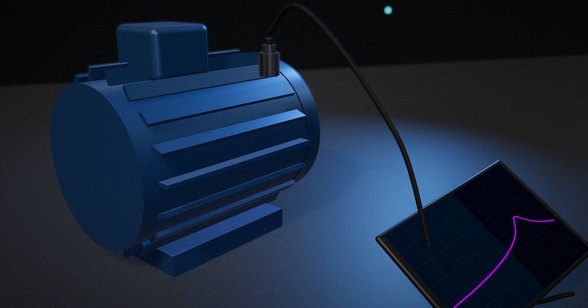
The sensor reads cleanly on the bench. Installed in the cabinet, next to a variable-frequency drive and a contactor, the same reading carries a 60 Hz ripple and spikes every time a motor starts. Someone adds a shielded cable and grounds the shield at both ends, and the ripple gets worse. Grounding and shielding sensor signals has a reputation for black magic because the same fix helps in one installation and hurts in the next. It stops being magic once you separate the three ways interference couples in, because each one has a different cure. This guide walks through the steps in order, with the numbers that tell you which problem you have.
Key Takeaways
- Identify the coupling path before you fix anything: electric field (capacitive), magnetic field (inductive) or conducted through a ground loop.
- A grounded shield stops electric fields well. It does very little against low-frequency magnetic fields: the skin depth of copper at 60 Hz is about 8.5 mm.
- Magnetic pickup is proportional to loop area. Twisting the pair and routing it away from power conductors does more than any shield at mains frequency.
- Grounding a shield at both ends helps above about 1 MHz and can create a ground loop at 50/60 Hz. A capacitor at one end gives you both behaviors.
- Terminate cable shields at the enclosure entry, not on the circuit board’s signal ground. Muncy’s “pin 1 problem” paper shows why.
The forum question: “I added a shield and it got worse”
That sentence, in some form, appears in nearly every discussion of noisy sensor wiring. The usual causes are predictable.
The interference was magnetic, from a nearby transformer, motor or power cable. A braided shield doesn’t block a 60 Hz magnetic field, so nothing improved, and the new cable had a larger loop area than the old twisted pair.
The shield was grounded at both ends, and the two grounds were at different potentials. Current now flows along the shield, and some of it couples into the signal conductors.
The shield was connected to the circuit’s signal ground inside the enclosure. Shield current now flows through the board’s ground copper on its way to chassis, and the voltage it develops appears at the input.
The input was single-ended. Any voltage difference between the sensor’s ground and the electronics’ ground adds directly to the measurement.
Step 1: Identify the coupling path
Before changing anything, figure out how the noise gets in. Analog Devices’ tutorial MT-095 on EMI and shielding describes the mechanisms: capacitive coupling from changing voltages, inductive coupling from changing currents, and conducted coupling through shared impedances.
Three quick tests separate them. Short the input at the sensor end: if the noise remains, it’s coming through the cable or the ground. Disconnect the shield at one end: if the noise changes a lot, shield current is involved. Move or reorient the cable relative to power conductors: if the noise changes with geometry, it’s field coupling. A spectrum helps too. Mains hum and its harmonics point to ground loops and magnetic coupling; sharp spikes at a drive’s switching frequency point to capacitive coupling or conducted noise.
Step 2: Reduce loop area, then balance the signal
Magnetic pickup is set by the area of the loop the signal and its return enclose. MT-095 gives the induced voltage as V = 2πf·B·A·cos θ × 10⁻⁸ volts, with B in gauss and A in cm². An illustrative example: a 60 Hz field of 0.1 gauss (10 µT) through a 10 cm² loop, which is two separate wires 5 mm apart over 20 cm, induces about 3.8 µV. That sounds small until you remember that a type K thermocouple produces about 40 µV/°C, so it’s roughly 0.1 °C of error.
Twisting the pair makes successive loops cancel, and MT-095 notes that the positive and negative loop areas sum to roughly zero. Keeping the cable perpendicular to the field and away from the source helps further; the tutorial notes that field intensity falls off quickly with distance.
Then make the measurement differential. A differential input responds to the voltage between the two signal wires and rejects voltage common to both, up to its common-mode rejection ratio. Illustratively, 1 V of common-mode hum into an input with 80 dB of CMRR leaves 100 µV, compared with the full 1 V on a single-ended input. Balanced source and lead impedances keep that rejection from collapsing in practice.
Step 3: Choose how to terminate the shield
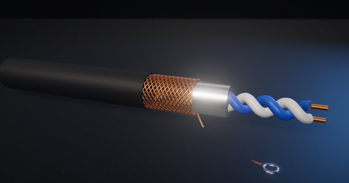
A shield works against electric fields by giving the interference a path to ground before it reaches the signal conductors. Where you connect it depends on frequency. MT-095 recommends:
- Below about 1 MHz, grounding the shield at one end is acceptable and avoids a low-frequency ground loop through the shield.
- Above about 1 MHz, ground both ends with 360° bonds, because a shield connected at one end becomes an antenna once the cable is a significant fraction of a wavelength. The tutorial treats a cable as electrically long above 1/20 of a wavelength, which at 100 MHz is 15 cm.
- When you need both, ground one end directly and the other through a low-inductance capacitor of 0.01 to 0.1 µF. The capacitor is a short at RF and an open circuit at mains frequency.
Don’t count on the shield for low-frequency magnetic fields. MT-095 gives the skin depth of copper as 6.6/√f centimeters; at 60 Hz that’s about 8.5 mm, far thicker than any cable braid. Magnetic fields at mains frequency are reduced by distance, orientation and loop area, or by high-permeability materials such as steel conduit or mu-metal.
Step 4: Bond the shield at the enclosure, not the circuit
Where the shield connects matters as much as whether it connects. Neil Muncy’s 1995 paper in the Journal of the Audio Engineering Society showed that a common equipment design practice, connecting cable shields to the circuit’s signal ground inside the equipment instead of to the chassis at the point of entry, makes the system susceptible to noise from shield current. He named it the “pin 1 problem” after the shield pin of the XLR connector, and argued it could be eliminated in manufacturing at almost no cost.
The principle applies to any sensor cable. Bond the shield to the metal enclosure where the cable enters, with a short, wide connection (ideally a 360° gland), so that shield current goes to chassis without flowing through the board’s ground copper.
Step 5: Lay out the board’s ground for the converter
Inside the enclosure, the problem is shared return impedance. Kester, Bryant and Byrne’s tutorial MT-031 on grounding data converters recommends at least one complete ground plane layer, and gives a number for why wires are a poor substitute: #22 AWG wire has about 20 nH per inch, so a transient of 10 mA/ns through one inch develops about 200 mV.
For converters with low digital current, MT-031 recommends treating the converter as an analog part: connect both its AGND and DGND pins to the analog ground plane with short connections, and decouple the digital supply close to the pins. Connecting DGND to a noisy system digital ground, the tutorial says, invites disaster. IEEE Std 1100, the recommended practice for powering and grounding electronic equipment, covers the facility side: safety grounding, bonding and how equipment grounds relate to the building’s grounding system. Safety grounding always takes priority; never lift a protective earth to break a ground loop.
Step 6: Verify in the real installation
Repeat the Step 1 tests after each change, in the actual cabinet with the drives and contactors running. Record the spectrum before and after. A change that doesn’t reduce the noise in the real installation isn’t a fix, however correct it looks on paper.
Grounding and shielding fixes by coupling path
| Coupling path | Typical symptom | Fix that works | Fix that doesn’t |
|---|---|---|---|
| Electric field (capacitive) | Spikes at drive switching edges, noise rising with frequency | Grounded shield, distance from high-dV/dt conductors | Twisting alone |
| Magnetic field (inductive), low frequency | 60 Hz hum that changes with cable position | Twisted pair, small loop area, distance, steel conduit | Copper braid shield |
| Ground loop (conducted) | 60 Hz hum that changes when grounds are connected or lifted | Differential input, single-point shield ground at LF, isolation | Adding more ground wires |
| Shield current into signal ground | Noise appears when shield is connected | Bond shield at enclosure entry (360°) | Connecting shield to board ground |
| High-frequency pickup on long cable | RF or drive noise on a cable longer than λ/20 | Shield bonded at both ends, or one end plus capacitor | Shield grounded at one end only |
How to put it to work
If you have an hour
On one noisy channel, run the three Step 1 tests (input shorted, shield lifted at one end, cable moved) and write down what changed. You’ll know which path dominates.
If you have a sprint
Fix the dominant path, then rerun the tests, and repeat until the noise floor is set by the sensor and electronics instead of the installation. Write the wiring rules (twisting, shield termination point, routing distance from power) into the installation instructions.
If you want it to last the product’s lifetime
Design the enclosure with 360° cable glands bonded to chassis, a dedicated shield termination point and differential inputs, so installers can’t get it wrong. Include a field check, such as a shorted-input noise capture, in commissioning.
The question to ask yourself: “Do I know whether this noise is electric, magnetic or a ground loop, or am I adding shields and hoping?”
Frequently asked questions
Should a sensor cable shield be grounded at one end or both ends?
It depends on frequency. Below about 1 MHz, one end is usually better because it avoids a ground loop through the shield. Above about 1 MHz, both ends with 360° bonds. When both matter, ground one end directly and the other through a 0.01–0.1 µF capacitor.
Why doesn’t my shielded cable stop 60 Hz hum?
Because 60 Hz hum usually comes from magnetic coupling or a ground loop, and a thin copper or aluminum shield barely affects low-frequency magnetic fields (copper’s skin depth at 60 Hz is about 8.5 mm). Twisted pairs, smaller loop areas, distance from power conductors and differential inputs are the effective fixes.
What is a ground loop in a sensor system?
A ground loop forms when the sensor and the electronics are grounded at two points with different potentials, so current flows through the signal return or the cable shield. The voltage that current develops adds to the measurement, usually as mains-frequency hum.
Where should I connect the cable shield?
To the metal enclosure at the point where the cable enters, with a short, wide connection, not to the circuit’s signal ground. Connecting shields to signal ground lets shield current flow through the board’s ground, which Muncy identified as the cause of the “pin 1 problem”.
Should I connect AGND and DGND together?
For data converters with low digital current, Analog Devices’ MT-031 recommends connecting both AGND and DGND pins to the analog ground plane close to the converter. The pin names describe the chip’s internal grounds, not where they must connect on your board.
Related reading: sensor noise sources explained, thermocouple vs RTD vs thermistor and the 4–20 mA current loop explained.
Sources
- Muncy, N. (1995). “Noise Susceptibility in Analog and Digital Signal Processing Systems.” Journal of the Audio Engineering Society, 43(6), 435–453. https://aes.org/publications/elibrary/elibrary-page/?id=7945
- IEEE (2005). IEEE Recommended Practice for Powering and Grounding Electronic Equipment (IEEE Std 1100-2005, the “Emerald Book”; now inactive-reserved). https://standards.ieee.org/ieee/1100/3055
- Analog Devices (2009). “EMI, RFI, and Shielding Concepts.” Analog Devices Tutorial MT-095, Rev. 0. https://www.analog.com/media/en/training-seminars/tutorials/MT-095.pdf
- Kester, W., Bryant, J., & Byrne, M. (2008). “Grounding Data Converters and Solving the Mystery of ‘AGND’ and ‘DGND’.” Analog Devices Tutorial MT-031, Rev. A. https://www.analog.com/media/en/training-seminars/tutorials/MT-031.pdf
- Ott, H. W. (2009). Electromagnetic Compatibility Engineering. Wiley. https://doi.org/10.1002/9780470508510